
Sound Design Basics: Subtractive Synthesis


Synthesis—generating and combining waveforms to produce complex sounds—can seem like quite a mountain to climb for early producers and new sound designers.
Unknown terms, unfamiliar concepts, and an array of vague knobs, switches, and graphs—where do you start?
These feelings are totally normal to have, but synthesis doesn’t have to be so overwhelming to dive into.
By breaking each concept down into steps, new producers and sound designers can further understand synthesis concepts wholistically, opening themselves up to opportunities for further growth.
And that’s exactly what we’re going to do in this article!
We’re going to be focusing mostly on the basics of subtractive synthesis. This is one of the more basic types of synthesis and involves taking away frequencies before combining waveforms. We’ll go over the tools we use to do this and their application.
In our exploration of subtractive synthesis, we’ll also discuss ideas that carry over into all branches of synthesis. Let’s jump into it!
The most important concept to understand when approaching synthesis (and potentially production in general) is signal flow.
This is the path that a signal (sound) takes from its source to the output. With this context, understanding the flow of signal in subtractive synthesis will be much easier.
Subtractive synthesis consists of various components that interact with each other. We’ll get to the components and their functions soon, but it’s important to first understand how signal travels from one component to the next.
In the frame of synthesis, something generates an initial signal, which is then processed by various components in the synthesizer. Each of these components has its own job and can be used to alter the signal as the sound designer pleases.
Note that these components in a synthesizer are similar to the plugins you’ll insert on a channel in your DAW. On a channel, sound enters the signal chain and moves through plugins along the way, being incrementally processed until it reaches the output.
A signal can generally flow through these synthesis components in two ways, in series or in parallel.

In the above diagram, signal is generated in Block 1 (this could be an oscillator), then sent to Block 2 (this could be a filter), then to Block 3 (this could be an amplifier), and then to Block 4 (this could be the output).
Because the signal travels linearly from Block 1 to Block 2 to Block 3 to Block 4, we say that these components are arranged “in series”.

In this diagram, signal again begins at the source, Block 1. It then splits and travels once to Block 2 and once again separately to Block 3. In this example, both Block 2 and 3 could be filters. Signal exits these filters and is mixed again at Block 4, the output.
Note that if Blocks 2 and 3 are set to have different parameters, this will sound different compared to the previous example.
We say that Blocks 2 and 3 are arranged “in parallel”.
Now that we understand the ways a signal can move through a synthesizer, let’s take a look at some components that we implement subtractive synthesis. We’ve actually mentioned the main three already: oscillators, filters, and amplifiers.
An oscillator acts as a source, generating and outputting a repeating waveform. On most synthesizers, this oscillator will have:
Oscillators in synthesizers - especially software synthesizers - will generally respond to MIDI input from a keyboard or MIDI controller and adjust the pitch accordingly.
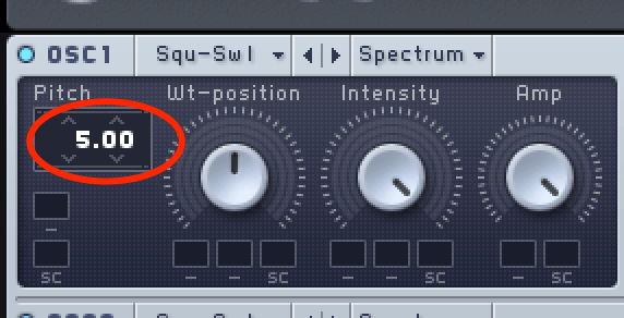
Many “soft synths” (software synthesizers) also allow for an oscillator to be transposed by semitone and cent increments.
For example, an oscillator’s pitch could be set to +5 semitones, and inputting a C on a MIDI controller would result in an F being played by the oscillator.
You can see that in this oscillator here, on Native Instrument’s Massive:
Oscillators in most synthesizers have the ability to output various waveshapes.
These shapes each repeat a different waveform, and each have their own timbre and frequency content. The common waveshapes that you’ll likely find are pictured below, taken from an oscillator in Xfer’s Serum:

Many soft synths will include an amplitude or level parameter for an oscillator. This is similar to an amplifier, which we’ll get to shortly.
The amplitude parameter controls the volume of the signal leaving the oscillator section of the synthesizer. Notice that both Massive and Serum have an amplitude or level parameter in their respective oscillator sections:


The oscillator is the most common component at the beginning of a subtractive synthesis patch. We’ll see how it’s integrated with the other components later.
Frequency-wise, most pitched audio signals (that could be defined by a musical note) consist of two components:
Sound in nature is caused by the movement of air molecules in a wave-like motion, and the rapid reflection of these waves off the surfaces inside an instrument causes these additional harmonics to be created.
The sound’s harmonic content determines the its characteristic timbre. The piano and guitar, for example, have different assortments of harmonics, so sound different even when playing the same note.
Subtractive synthesis is different from other synthesis methods in the sense that the sound designer focuses on removing harmonic content from a sound, and this is often done using a filter. These filters often come after oscillators in a subtractive synthesis chain.
If you’re familiar with how an EQ works, a filter is just another name for a band on an EQ. These bands can be used to boost or attenuate (decrease) the level of certain frequency ranges in a sound.
Boosting and cutting, filters are the best way to sculpt the harmonic content of a sound.
The most common filter shapes are high-pass / low-cut and low-pass / high-cut filters (HPF’s / LPF’s), low-shelf and high-shelf filters, bell filters, and notch filters.
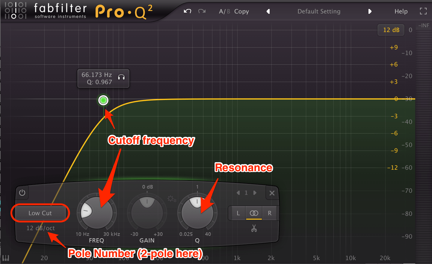
A high-pass / low-cut filter is used to attenuate and cut out harmonic content below a certain frequency. This frequency is called the cutoff frequency, and is usually adjustable in the filters found on synthesizers. We’re using FabFilter’s Pro Q 2 for a demonstration.
These filters also tend to have a Q or resonance parameter. Increasing this will boost signal at and immediately around the cutoff frequency.
Lastly, HPF’s tend to have a pole number. This parameter determines how steeply the filter drops off to the left of the cutoff frequency.
Common pole numbers are 1-4, and measure how many increments of 6 dB a filter attenuates the signal per octave. Put simply, a 1-pole filter will attenuate signal 6 dB over the course of an octave, a 2-pole filter will attenuate 12 dB, a 3-pole 18 dB, and a 4-pole 24 dB.
It’s important to note that “high pass” and “low cut” are two names for the same thing. The filter allows high frequencies to “pass” through, or it cuts out the lower frequencies. It’s just a matter of perspective.
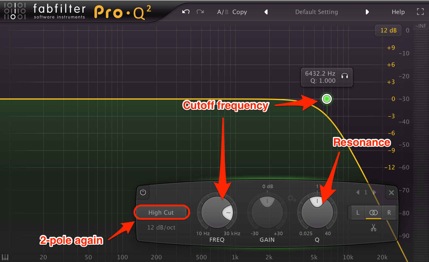
Low-pass / high-cut filters are very similar, but occur at the opposite side of the frequency spectrum. They can attenuate and cut out harmonic content above a set cutoff frequency. Q / resonance and pole numbers work the exact same way for these filters as for HPF’s.
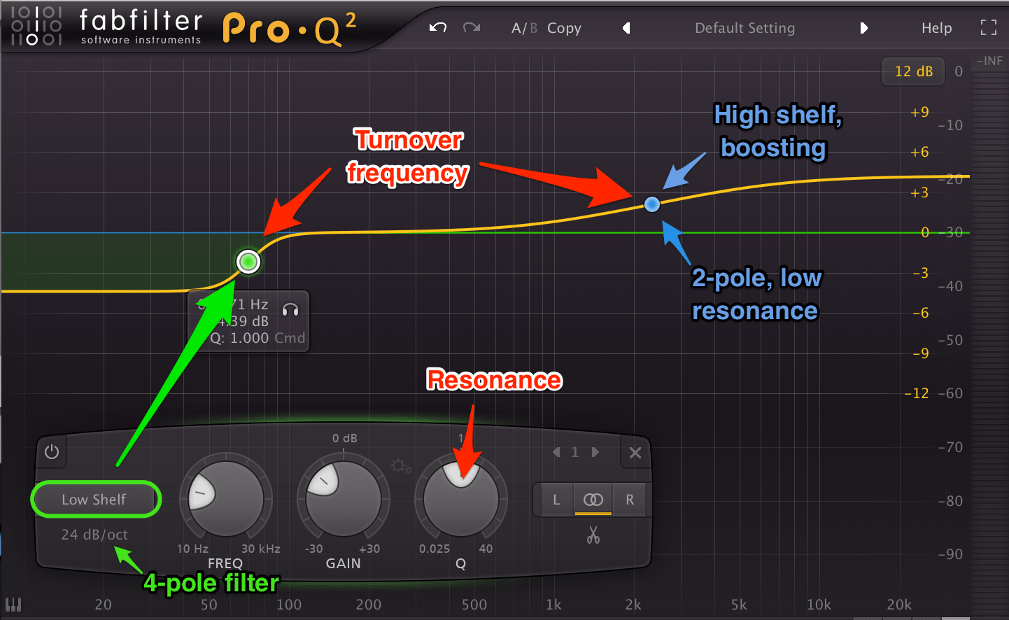
Shelf filters are similar to pass / cut filters, but vary in a couple ways. They have a similar parameter to a cutoff frequency called a turnover frequency, which functions more or less the same way. Q and pole number affect shelf filters similarly to pass / cut filters.
However, shelf filters have an adjustable gain parameter as well. Thus, they can be used to either boost or attenuate frequencies, creating an S-shape in which the filter plateaus (unlike a pass / cut filter). Using shelf filters to attenuate frequencies is therefore a bit softer than full-out HPF’s or LPF’s.

These are the most common type of filter, able to boost or attenuate a set range of frequencies in a signal. Similar to cutoff and turnover frequencies, bell filters have a center frequency placed in the center of the range.
This range can be set by the Q or resonance parameter, with lower values including a wider range of frequencies and higher values including a narrower range. The range is either boosted or attenuated with a gain parameter.
Bell filters can technically have pole numbers as well, but not all filters offer this flexibility. FabFilter’s Pro Q 2 equalizer allows pole number to be set on all filters, Ableton’s native EQ only allows 2 pole number settings on LPF’s and HPF’s (1- and 4-pole). Again, pole numbers on bell filters function the same as with the previous examples.

The last basic filter shape is a notch filter. These filters can cut out a range of frequencies anywhere in the frequency spectrum. Again, notch filters use a center frequency. Q and pole number once again have the same functions. Note that a bell filter with a higher Q value and very low gain will act similarly to a notch filter.
While you may be used to the idea of an amplifier making something louder (like a guitar/mic amp), an amplifier in this context simply determines the level of the signal.
It may often simply function as a gain parameter, and can also be used to sculpt the duration of a sound using modulation...
In the world of sound design, boring is the worst possible outcome. The more a sound can vary over time in timbre, amplitude, pitch, etc. the more attention it will draw.
Not every sound calls for a ton of time-based variation, but at least some can help to make a sound more organic and lively.
Modulation is the most common way to apply these types of variation. We’re able to automate the movement of a parameter in a synthesizer using a few different “control signals”, the most common of which are LFO’s and envelope generators.
These control signals can be applied to a parameter and move said parameter through a range of positions (the range can be set). The parameter will follow the shape of the LFO or envelope generator.
LFO’s are exactly what they sound like: oscillators generating very low frequency waves.
Often, these waves fall below 20 Hz - the lower limit of human hearing - and enter the subsonic range. LFO’s can be set to produce a variety of repeating waveshapes, similar to the normal oscillators available in many synthesizers.
These LFO’s can be used to modulate other parameters in a synthesizer. They will generally have adjustable waveshape and rate (frequency) parameters. Serum’s LFO, pictured below, has a totally customizable shape. Like most LFO’s, it also offers rates that are synced to a rhythmic value, linked to the tempo.
This LFO is synced to a quarter note, so the LFO output values through waveshape from left to right over the duration of one quarter note.

For example, an LFO can be set to have a basic sine wave as the waveshape and a rate of 2 Hz. This could be applied to the amplifier, causing the amplitude of the signal to rise and fall with the movement of the slow sine wave.
The amplitude will increase as the sine wave rises, decrease as it falls, and return to the starting position. Since the LFO is set to a rate of 2 Hz, this rise and fall will occur twice per second.
An LFO could also be applied to the pitch of an oscillator to create vibrato. In this scenario, the LFO would only modulate the pitch a small amount (less than a semitone above and below the played pitch) and oscillate at somewhere between 4-7 Hz.
Because LFO’s create a repeated signal that modulates a parameter, they are best used to create a repeating modulation pattern. Think of the wobbling chord synths common to future bass. These are created with an LFO modulating the amplifier, and perhaps a filter cutoff frequency as well.
But sometimes a repeating modulation signal isn’t what’s needed. Sometimes we just want a one-time movement of a certain parameter. This is possible with an envelope generator.
These create what’s called an envelope, a one-shot signal that can be used to modulate another parameter.
An envelope is comprised of several sections over time, each of which can usually be adjusted. These sections are represented with the acronym “ADSR”, standing for attack time, decay time, sustain level, and release time.
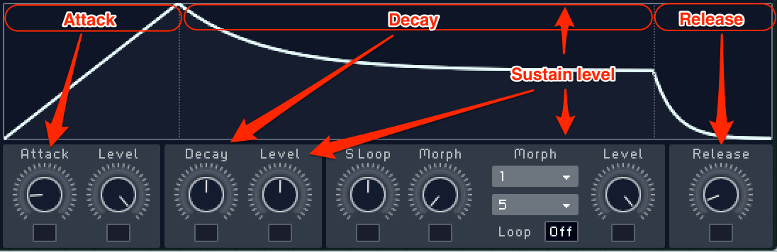
In the set attack time, the signal goes from silence to full amplitude, usually measured in milliseconds (ms).
Lower attack time values will result in the envelope reaching full amplitude quickly, while higher values will cause a gradual ramp from low to high amplitude.
Once an envelope reaches maximum amplitude, it can then decay down to a lower level over a period of time. The decay time parameter of an envelope will determine how long (in ms) the signal takes to drop to this lower level.
The sustain level parameter determines what this lower level is, and is usually measured in negative dB values.
At a sustain value of -4 dB for example, the envelope will rise from nothing to full amplitude according to the attack time and then drop 4 dB according to the decay time.
Notice that a sustain value of 0 dB (no change from the envelope’s maximum amplitude) effectively results in no decay stage.
At some point, the envelope is triggered to “release”, and signal drops from the sustain level to nothing again. The time that this takes (again in ms) is determined by the release time.
The most common use of envelope generators is to determine the amplitude of a sound over time, and thus one would be applied to an amplifier.
When a note is played, the envelope is triggered and raises the amplitude to a maximum according to the attack time.
After reaching full strength, it decays to the sustain level according to the decay time.
Once the note is released, signal reduces to nothing according to the release time.
Note that the values you choose have a huge impact on the character of a sound. Short attack values, short decay values, and a sustain level of -inf dB will result in short, plucky sounds.
Long attacks and higher sustain values result in swelling pad-like sounds. Approach your ADSR values with intent and dial in that sound in your head!
The most basic subtractive synthesis setup would consist of an oscillator running into a filter and then an amplifier, all in series. Two or more instances of this chain could run in parallel, and then be mixed after the filters or amplifiers.
Modulators can then be used to provide movement to anything from the oscillator’s pitch to the filter’s cutoff frequency to the amplifier’s gain.

The diagram above shows two oscillators running into their own filters. The outputs from these filters are mixed at the amplifier. LFOs or envelope generators can be applied to parameters on the oscillators (e.g. pitch) or filters (e.g. cutoff frequency).
An envelope generator is applied to the level of the amplifier to control the shape of the sound over time.
Obviously, there are more complicated ways to use subtractive synthesis. There are also other synthesis methods like additive synthesis, FM synthesis, granular synthesis, and more that churn out different results.
But a large majority of synthesis comes down to frequency content, amplitude, and modulation, all of which can be approached with these simple subtractive methods. Getting a good handle of these concepts and developing the ability to use them purposefully is a huge step to improving your skills as a sound designer.
What information was helpful? Do you have any questions?
Feel free to reach out in the comments below!
Unknown terms, unfamiliar concepts, and an array of vague knobs, switches, and graphs—where do you start?
These feelings are totally normal to have, but synthesis doesn’t have to be so overwhelming to dive into.
By breaking each concept down into steps, new producers and sound designers can further understand synthesis concepts wholistically, opening themselves up to opportunities for further growth.
And that’s exactly what we’re going to do in this article!
We’re going to be focusing mostly on the basics of subtractive synthesis. This is one of the more basic types of synthesis and involves taking away frequencies before combining waveforms. We’ll go over the tools we use to do this and their application.
In our exploration of subtractive synthesis, we’ll also discuss ideas that carry over into all branches of synthesis. Let’s jump into it!
Signal Flow in Synthesis
The most important concept to understand when approaching synthesis (and potentially production in general) is signal flow.
This is the path that a signal (sound) takes from its source to the output. With this context, understanding the flow of signal in subtractive synthesis will be much easier.
Subtractive synthesis consists of various components that interact with each other. We’ll get to the components and their functions soon, but it’s important to first understand how signal travels from one component to the next.
In the frame of synthesis, something generates an initial signal, which is then processed by various components in the synthesizer. Each of these components has its own job and can be used to alter the signal as the sound designer pleases.
Note that these components in a synthesizer are similar to the plugins you’ll insert on a channel in your DAW. On a channel, sound enters the signal chain and moves through plugins along the way, being incrementally processed until it reaches the output.
A signal can generally flow through these synthesis components in two ways, in series or in parallel.
In the above diagram, signal is generated in Block 1 (this could be an oscillator), then sent to Block 2 (this could be a filter), then to Block 3 (this could be an amplifier), and then to Block 4 (this could be the output).
Because the signal travels linearly from Block 1 to Block 2 to Block 3 to Block 4, we say that these components are arranged “in series”.
In this diagram, signal again begins at the source, Block 1. It then splits and travels once to Block 2 and once again separately to Block 3. In this example, both Block 2 and 3 could be filters. Signal exits these filters and is mixed again at Block 4, the output.
Note that if Blocks 2 and 3 are set to have different parameters, this will sound different compared to the previous example.
We say that Blocks 2 and 3 are arranged “in parallel”.
Synthesis components
Now that we understand the ways a signal can move through a synthesizer, let’s take a look at some components that we implement subtractive synthesis. We’ve actually mentioned the main three already: oscillators, filters, and amplifiers.
Oscillators
An oscillator acts as a source, generating and outputting a repeating waveform. On most synthesizers, this oscillator will have:
- An adjustable frequency / pitch (measured in Hz / musical note respectively)
- A waveshape (sine, triangle, square, sawtooth, etc.)
- An amplitude (measured in dB or a percentage with 0% being silent and 100% being full level)
Oscillators in synthesizers - especially software synthesizers - will generally respond to MIDI input from a keyboard or MIDI controller and adjust the pitch accordingly.
Many “soft synths” (software synthesizers) also allow for an oscillator to be transposed by semitone and cent increments.
For example, an oscillator’s pitch could be set to +5 semitones, and inputting a C on a MIDI controller would result in an F being played by the oscillator.
You can see that in this oscillator here, on Native Instrument’s Massive:
Oscillators in most synthesizers have the ability to output various waveshapes.
These shapes each repeat a different waveform, and each have their own timbre and frequency content. The common waveshapes that you’ll likely find are pictured below, taken from an oscillator in Xfer’s Serum:
Many soft synths will include an amplitude or level parameter for an oscillator. This is similar to an amplifier, which we’ll get to shortly.
The amplitude parameter controls the volume of the signal leaving the oscillator section of the synthesizer. Notice that both Massive and Serum have an amplitude or level parameter in their respective oscillator sections:
The oscillator is the most common component at the beginning of a subtractive synthesis patch. We’ll see how it’s integrated with the other components later.
Filters
Frequency-wise, most pitched audio signals (that could be defined by a musical note) consist of two components:
- A fundamental frequency (located at that musical note)
- And a series of harmonics, or accompanying overtones above the fundamental frequency
Sound in nature is caused by the movement of air molecules in a wave-like motion, and the rapid reflection of these waves off the surfaces inside an instrument causes these additional harmonics to be created.
The sound’s harmonic content determines the its characteristic timbre. The piano and guitar, for example, have different assortments of harmonics, so sound different even when playing the same note.
Subtractive synthesis is different from other synthesis methods in the sense that the sound designer focuses on removing harmonic content from a sound, and this is often done using a filter. These filters often come after oscillators in a subtractive synthesis chain.
If you’re familiar with how an EQ works, a filter is just another name for a band on an EQ. These bands can be used to boost or attenuate (decrease) the level of certain frequency ranges in a sound.
Boosting and cutting, filters are the best way to sculpt the harmonic content of a sound.
The most common filter shapes are high-pass / low-cut and low-pass / high-cut filters (HPF’s / LPF’s), low-shelf and high-shelf filters, bell filters, and notch filters.
High-pass / Low-cut
A high-pass / low-cut filter is used to attenuate and cut out harmonic content below a certain frequency. This frequency is called the cutoff frequency, and is usually adjustable in the filters found on synthesizers. We’re using FabFilter’s Pro Q 2 for a demonstration.
These filters also tend to have a Q or resonance parameter. Increasing this will boost signal at and immediately around the cutoff frequency.
Lastly, HPF’s tend to have a pole number. This parameter determines how steeply the filter drops off to the left of the cutoff frequency.
Common pole numbers are 1-4, and measure how many increments of 6 dB a filter attenuates the signal per octave. Put simply, a 1-pole filter will attenuate signal 6 dB over the course of an octave, a 2-pole filter will attenuate 12 dB, a 3-pole 18 dB, and a 4-pole 24 dB.
It’s important to note that “high pass” and “low cut” are two names for the same thing. The filter allows high frequencies to “pass” through, or it cuts out the lower frequencies. It’s just a matter of perspective.
Low-pass / high-cut
Low-pass / high-cut filters are very similar, but occur at the opposite side of the frequency spectrum. They can attenuate and cut out harmonic content above a set cutoff frequency. Q / resonance and pole numbers work the exact same way for these filters as for HPF’s.
Low-shelf & high-shelf filters
Shelf filters are similar to pass / cut filters, but vary in a couple ways. They have a similar parameter to a cutoff frequency called a turnover frequency, which functions more or less the same way. Q and pole number affect shelf filters similarly to pass / cut filters.
However, shelf filters have an adjustable gain parameter as well. Thus, they can be used to either boost or attenuate frequencies, creating an S-shape in which the filter plateaus (unlike a pass / cut filter). Using shelf filters to attenuate frequencies is therefore a bit softer than full-out HPF’s or LPF’s.
Bell filters
These are the most common type of filter, able to boost or attenuate a set range of frequencies in a signal. Similar to cutoff and turnover frequencies, bell filters have a center frequency placed in the center of the range.
This range can be set by the Q or resonance parameter, with lower values including a wider range of frequencies and higher values including a narrower range. The range is either boosted or attenuated with a gain parameter.
Bell filters can technically have pole numbers as well, but not all filters offer this flexibility. FabFilter’s Pro Q 2 equalizer allows pole number to be set on all filters, Ableton’s native EQ only allows 2 pole number settings on LPF’s and HPF’s (1- and 4-pole). Again, pole numbers on bell filters function the same as with the previous examples.
Notch filters
The last basic filter shape is a notch filter. These filters can cut out a range of frequencies anywhere in the frequency spectrum. Again, notch filters use a center frequency. Q and pole number once again have the same functions. Note that a bell filter with a higher Q value and very low gain will act similarly to a notch filter.
Amplifiers
While you may be used to the idea of an amplifier making something louder (like a guitar/mic amp), an amplifier in this context simply determines the level of the signal.
It may often simply function as a gain parameter, and can also be used to sculpt the duration of a sound using modulation...
Modulation
In the world of sound design, boring is the worst possible outcome. The more a sound can vary over time in timbre, amplitude, pitch, etc. the more attention it will draw.
Not every sound calls for a ton of time-based variation, but at least some can help to make a sound more organic and lively.
Modulation is the most common way to apply these types of variation. We’re able to automate the movement of a parameter in a synthesizer using a few different “control signals”, the most common of which are LFO’s and envelope generators.
These control signals can be applied to a parameter and move said parameter through a range of positions (the range can be set). The parameter will follow the shape of the LFO or envelope generator.
Low Frequency Oscillators (LFO's)
LFO’s are exactly what they sound like: oscillators generating very low frequency waves.
Often, these waves fall below 20 Hz - the lower limit of human hearing - and enter the subsonic range. LFO’s can be set to produce a variety of repeating waveshapes, similar to the normal oscillators available in many synthesizers.
These LFO’s can be used to modulate other parameters in a synthesizer. They will generally have adjustable waveshape and rate (frequency) parameters. Serum’s LFO, pictured below, has a totally customizable shape. Like most LFO’s, it also offers rates that are synced to a rhythmic value, linked to the tempo.
This LFO is synced to a quarter note, so the LFO output values through waveshape from left to right over the duration of one quarter note.
For example, an LFO can be set to have a basic sine wave as the waveshape and a rate of 2 Hz. This could be applied to the amplifier, causing the amplitude of the signal to rise and fall with the movement of the slow sine wave.
The amplitude will increase as the sine wave rises, decrease as it falls, and return to the starting position. Since the LFO is set to a rate of 2 Hz, this rise and fall will occur twice per second.
An LFO could also be applied to the pitch of an oscillator to create vibrato. In this scenario, the LFO would only modulate the pitch a small amount (less than a semitone above and below the played pitch) and oscillate at somewhere between 4-7 Hz.
Because LFO’s create a repeated signal that modulates a parameter, they are best used to create a repeating modulation pattern. Think of the wobbling chord synths common to future bass. These are created with an LFO modulating the amplifier, and perhaps a filter cutoff frequency as well.
Envelope generators
But sometimes a repeating modulation signal isn’t what’s needed. Sometimes we just want a one-time movement of a certain parameter. This is possible with an envelope generator.
These create what’s called an envelope, a one-shot signal that can be used to modulate another parameter.
An envelope is comprised of several sections over time, each of which can usually be adjusted. These sections are represented with the acronym “ADSR”, standing for attack time, decay time, sustain level, and release time.
Attack time
In the set attack time, the signal goes from silence to full amplitude, usually measured in milliseconds (ms).
Lower attack time values will result in the envelope reaching full amplitude quickly, while higher values will cause a gradual ramp from low to high amplitude.
Decay time
Once an envelope reaches maximum amplitude, it can then decay down to a lower level over a period of time. The decay time parameter of an envelope will determine how long (in ms) the signal takes to drop to this lower level.
Sustain
The sustain level parameter determines what this lower level is, and is usually measured in negative dB values.
At a sustain value of -4 dB for example, the envelope will rise from nothing to full amplitude according to the attack time and then drop 4 dB according to the decay time.
Notice that a sustain value of 0 dB (no change from the envelope’s maximum amplitude) effectively results in no decay stage.
Do you want to learn music production faster than ever? - Click Here
Release time
At some point, the envelope is triggered to “release”, and signal drops from the sustain level to nothing again. The time that this takes (again in ms) is determined by the release time.
The most common use of envelope generators is to determine the amplitude of a sound over time, and thus one would be applied to an amplifier.
When a note is played, the envelope is triggered and raises the amplitude to a maximum according to the attack time.
After reaching full strength, it decays to the sustain level according to the decay time.
Once the note is released, signal reduces to nothing according to the release time.
Note that the values you choose have a huge impact on the character of a sound. Short attack values, short decay values, and a sustain level of -inf dB will result in short, plucky sounds.
Long attacks and higher sustain values result in swelling pad-like sounds. Approach your ADSR values with intent and dial in that sound in your head!
Most common setup in subtractive synthesis
The most basic subtractive synthesis setup would consist of an oscillator running into a filter and then an amplifier, all in series. Two or more instances of this chain could run in parallel, and then be mixed after the filters or amplifiers.
Modulators can then be used to provide movement to anything from the oscillator’s pitch to the filter’s cutoff frequency to the amplifier’s gain.
The diagram above shows two oscillators running into their own filters. The outputs from these filters are mixed at the amplifier. LFOs or envelope generators can be applied to parameters on the oscillators (e.g. pitch) or filters (e.g. cutoff frequency).
An envelope generator is applied to the level of the amplifier to control the shape of the sound over time.
Conclusion
Obviously, there are more complicated ways to use subtractive synthesis. There are also other synthesis methods like additive synthesis, FM synthesis, granular synthesis, and more that churn out different results.
But a large majority of synthesis comes down to frequency content, amplitude, and modulation, all of which can be approached with these simple subtractive methods. Getting a good handle of these concepts and developing the ability to use them purposefully is a huge step to improving your skills as a sound designer.
What information was helpful? Do you have any questions?
Feel free to reach out in the comments below!
Do you want better Serum presets?
Download our free Ultimate Serum Library and improve your sound library today.